 |
|||
|
|
|||
|
Page Title:
T-45 high-speed flight characteristics (found in NATOPS) |
|
||
| ||||||||||
|
|  T-45A/C TS, ADV & IUT Aero-02
High-Speed Flight
3.
Vortex generators (VGs)
Sg 2, fr 13
Fig 11: Vortex
a.
Single row of 20 installed on each wing at 25%
Generators on the
of wing chord
T-45
b.
Reduce boundary layer growth and delay
forward migration of the shock and shock-
induced separation
c.
Primary purpose to improve longitudinal stability
at speeds above Mach 0.80
4.
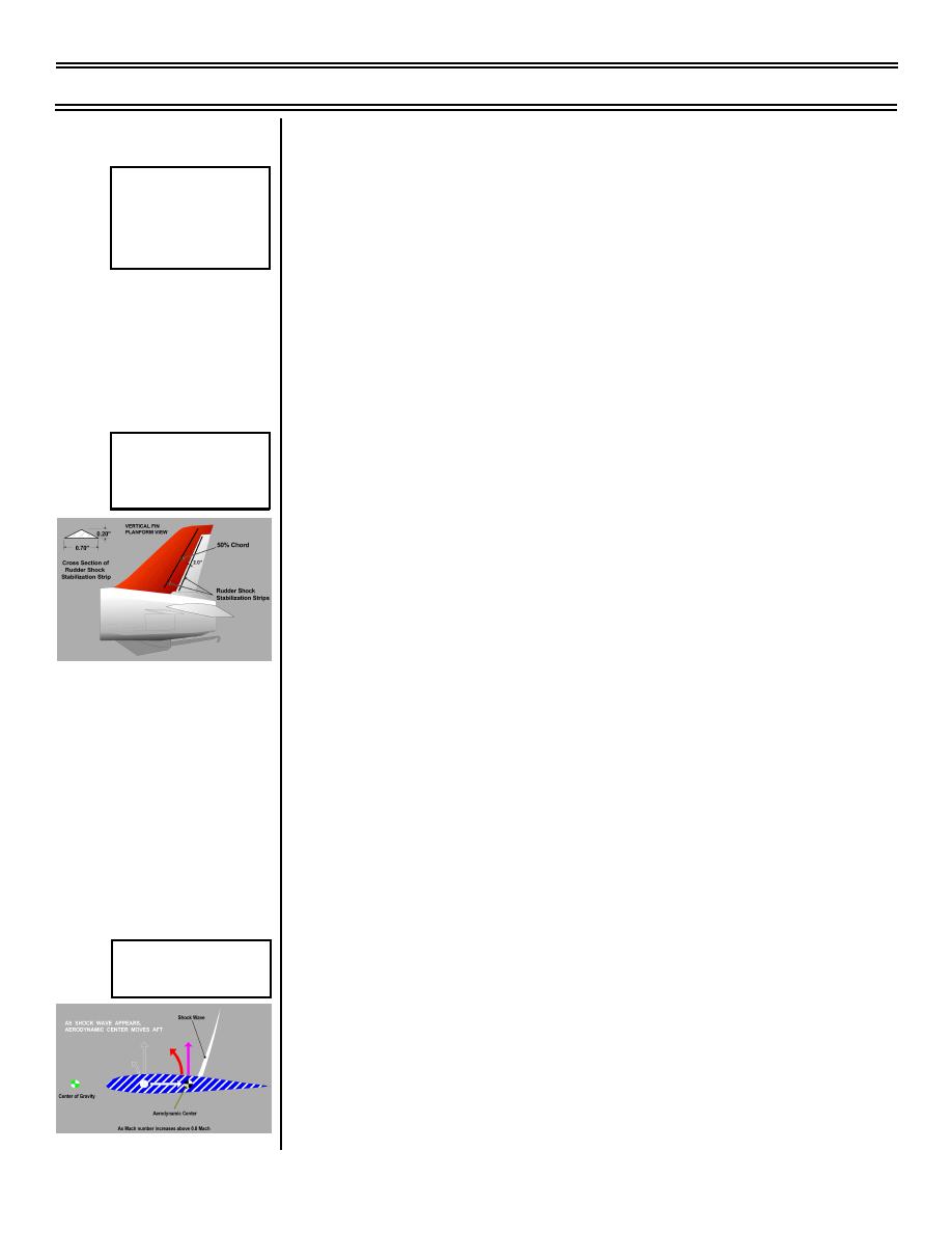
Rudder shock stabilization strips
Sg 2, fr 17
Rudder Shock
Stabilization Strips
a.
Two located on each side of vertical tail, one at
50% of tail chord and one just aft of rudder
hinge line
b.
Installed after uncontrollable rudder oscillation
(rudder buzz) occurred at high speed,
Mach 0.9-0.95
(1) Rudder buzz results from unstable shock
wave motion and shock-induced separation
(2) Strips stabilize the shock wave motion
c.
Developed after computational flowfield
analysis and flight tests
C. T-45 high-speed flight characteristics (found in
NATOPS) 1.7.1.4.6
1.
Capable of transonic flight ONLY in a dive and in a
clean configuration
Sg 2, fr 18
Aft Movement of the
2.
Speeds up to Mach 1.04 have been achieved
Center of Pressure
a.
No pronounced nose-down pitch transient
during acceleration
b.
High-speed acceleration is moderate and Mach
effect is gradual
Page 2-20
(9-99) Original
|
|
Privacy Statement - Press Release - Copyright Information. - Contact Us |