 |
|||
|
|
|||
|
|
|||
| ||||||||||
|
|  T-45A/C TS, E2-C2, ADV & IUT Aero-06/07
NATOPS Performance Charts / Charts and Exam Review
2.
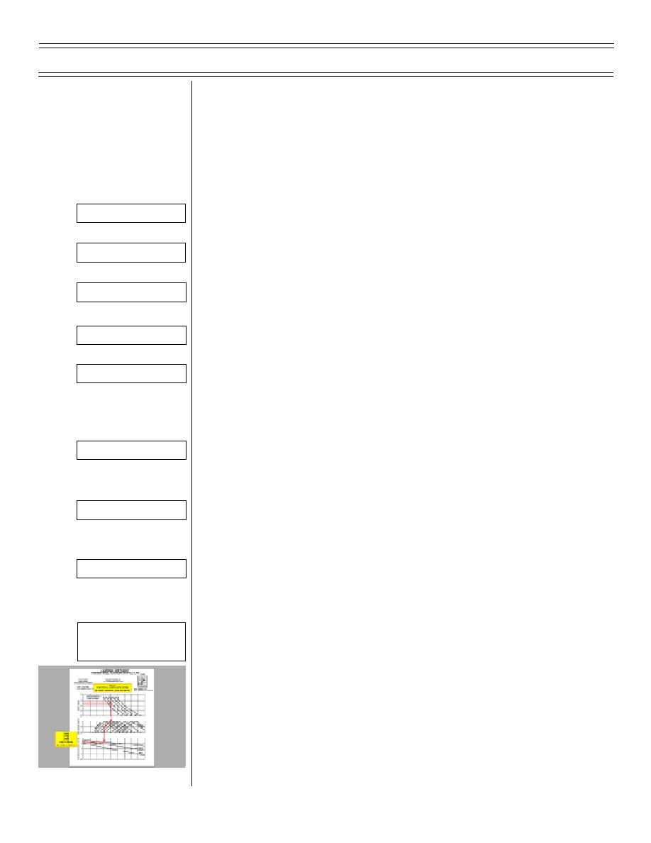
Landing distance data is for a normal 17-unit AOA
approach and landing using moderate braking
coefficients
3.
Landing Distance Computation
a.
Enter chart with the density ratio
Overlay 1
b.
Extend line horizontally from density ratio to
Overlay 2
approach gross weight line
c.
From the intersection of the density ratio line
Overlay 3
and approach gross weight line extend a line
vertically down to the wind speed graph
Overlay 4
d.
From the wind speed baseline, parallel the
nearest headwind or tailwind guideline down to
Overlay 5
the appropriate headwind or tailwind component
in knots
e.
From the intersection of the line paralleling the
guideline and the headwind or tailwind
Overlay 6
component project a line down vertically to the
ground roll distance graph
f.
Continue the line down to the appropriate
Overlay 7
runway condition reference line
g.
From the intersection of the vertical line and
runway condition reference line, project a
Overlay 8
horizontal line to the left to determine ground
roll
4.
For total landing distance from 50 feet over the
Sg3, fr 18
runway, add 715 feet to computed ground roll
Landing Distance
distance, e.g. crossing approach end of runway at
50 feet
(9-99) Original
Page 6-12
|
|
Privacy Statement - Press Release - Copyright Information. - Contact Us |
