 |
|||
|
|
|||
|
|
|||
| ||||||||||
|
|  T-45A/C TS, E2-C2, ADV & IUT Aero-03
Slow-Speed Flight, Stall and Spin, and AOA System
3.
A change in AOA is easier to detect than a change
in airspeed; in landing configuration, 1 unit AOA is
equal to 3 KIAS
4.
Changes in flap settings are compensated for
5.
Instrument scan is reduced
6.
Pilot workload is reduced by eliminating the need for
weight and speed calculations
Sg 3, fr 5
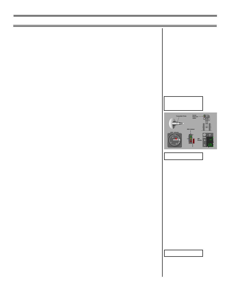
E. AOA components
AOA Components
(4 overlays)
1.
Probe transmitter
a.
Probe aligns itself with the relative wind and
sends out electrical signal
b.
Transmitter amplifies signal and sends it to
other system components
2.
Carrier approach lights
Overlay 1
a.
Located on nose landing gear strut
b.
Used to aid LSO in determining if T-45 is being
flown at optimum AOA
c.
Controlled by AOA indicator; red, amber, and
green lights show if AOA is low, optimum, or
high
3.
Rudder pedal shaker
a.
Controlled by forward cockpit AOA indicator
b.
Provides an artificial stall warning through the
left rudder pedal
4.
AOA indicator
Overlay 2
a.
Indicates AOA in nondimensional units; a
specific unit is used as a reference for each
phase of flight
(9-99) Original
Page 3-27
|
|
Privacy Statement - Press Release - Copyright Information. - Contact Us |
