Flight Controls
T-45A UJPT, E2-C2, ADV, & IUT Eng-11
NOTE: Due to the design of the T-45A, a split
slat condition is highly unlikely. Be advised that
this is not an impossibility and would be a very
dangerous situation should it occur.
C.
Speed brake system 1.4.19.3.1, 1.4.19.2.1,
1.4.19.3
Sg 3, fr 8
HYD 1
1.
Components
HYD 1 RETURN
ELECTRICAL
FWD/AFTThrottle
Speed Brake Switches
a.
Left/right speed brakes
(1) Location: one speed brake panel
SpeedBrake
SpeedBrake
on each side of aft fuselage
Actuator
Actuator
Speed Brake
Package Assembly
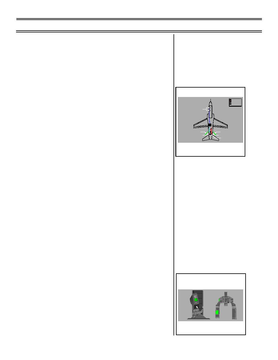
SPEED BRAKE SYSTEM
(2) Function: increase drag, decrease
COMPONENTS--SIMPLIFIED
speed for maneuvering when
needed
NOTE: The use of speed brakes
during approach allows the engine
to be spooled up (operate at a
higher rpm) without an increase in
airspeed. (Important due to slow
spool up time of engine.)
b.
Hydraulic actuator
(1) Location: attached to each speed
brake door and anchored inside
fuselage
(2) Function: extends or retracts
speed brakes depending on
position of a hydraulically operated
Sg 3, fr 9
slide valve
(1 Overlay)
2.
Cockpit controls/switches/indicators
GTS
ROTATION
SPD BRK
SPD BRK FULL
a.
SPD BRK advisory light
ECA
MANUAL FUEL
NOSE WHL STR
(1) Location: on advisory panel (left
ANTI-SKID
instrument panel) in both cockpits
SPEED BRAKE CONTROLS/
INDICATORS
Page 11-27
(8-03) Original


 Previous Page
