T-45A UJPT, E2-C2, ADV, & IUT Eng-02
Engine
Sg 1, fr 1
PRESENTATION
Lesson Organization
I.
Engine system major components identification
Sg 1, fr 2
1.4.6.3.1
Chamber
Internal Gearbox
N2 Turbine
N1 Turbine
A.
Engine: twin spool, medium bypass, axial flow
N1 Turbine
Bearing
turbofan producing approximately 5,527 lb of
thrust
Oil Tank
Location
N2 Turbine
Intershaft
Bearing
Bearing
Bearing
HS Gearbox
Front Bearing
Engine Fuel
Controls Cambox
B.
Engine fuel system (as opposed to aircraft fuel
BASIC ENGINE DIAGRAM
system): engine-driven low- and high-pressure
fuel pumps with manual and automatic fuel
Sg 1, fr 3
metering controls
Engine Fuel System Block
Diagram
C.
Engine lubrication system: self-contained,
engine-driven, full-flow recirculating system
Sg 1, fr 4
Engine Lubrication System Block
Diagram
D.
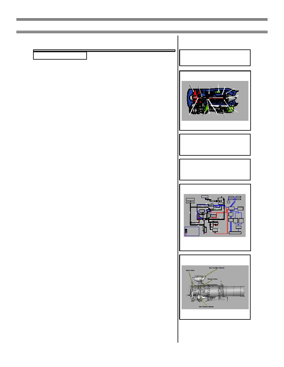
Engine starting system
1.
Gas turbine starter (GTS)
Sg 1, fr 5
TO ATMOSPHERE
ADVISORY LIGHTS
WING TANK
BOOST PUMP
ROTATION
GTS
FUEL
GTS OIL
FUELVENT
SHUTOFF
VALVE
TANK
ROTATION
GTS
a.
Location: airframe-mounted on central
TANK
LOW PRESSURE
FILTER
SHUTOFF VALVE
ECA
CHECK VALVE
FUEL/OIL
FUEL SPILL
100RPMN
PUMP
1
VALVE
fuselage above engine
DIST.
START
UNIT
ALTITUDE
CONTROL
UNIT
SWITCH
UNIT
OIL PRESSURE SWITCH
ENGINE
SWITCH
DC STARTER
GTS
MOTOR
SPEED PROBE
b.
Description: self-contained, two-stage
ENGINE
GTS
GTS
SWITCH
START
START
DUMP VALVE
BUTTON
BUTTON
PURGE
VALVE
TO ATMOSPHERE
START
VALVE
air-starting system, powers the air
PILOT
IGNITION
DUMP VALVE
SWITCH
LEGEND
AIR
FUEL
STARTER
ENGINE
DRAIN
SPILL FUEL
MOTOR
VALVE
OIL
AIR
SPEED PROBE
ESSENTIALSERVICESBUS
turbine starter which provides engine
DRAIN
ELECTRICAL COMMAND
OVERBOARD
ELECTRICAL MONITORING
rotation
ENGINE STARTING SYSTEM BLOCK
DIAGRAM
2.
Air turbine starter (ATS)
Sg 1, fr 6
a.
Location: mounted to external engine
gearbox
b.
Description: consists of a turbine
driven by air from the GTS. Air turbine
starter drives engine N2 shaft through
the accessory gearbox and provides
ENGINE START SYSTEM
rotation assistance until approximately
45% rpm has been achieved
(8-03) Original
Page 2-3


 Previous Page
