Hydraulic Subsystems
T-45A UJPT, E2-C2, ADV, & IUT Eng-13
(1) Mechanically operated by landing
gear
(2) Remains open when gear
extended
B.
Controls and indicators
Sg 1, fr 7
1.
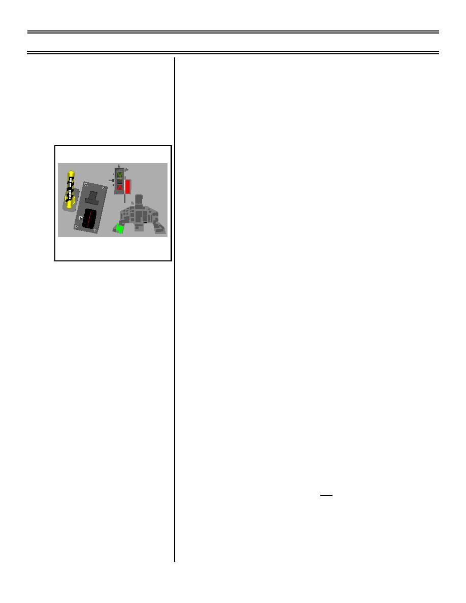
LDG GEAR handle
W
H
E
E
L
LDG
a.
Location: left forward console, both
GEAR
S
DOO
R
NOSE
LEFT
cockpits
RIGH
T
UP
TONE
b.
Purpose: UP raises gear, DN lowers
DN
gear
LANDING GEAR CONTROLS AND
INDICATORS
c.
Detented: pull to release
d.
Electromechanical: with aircraft on
deck and LDG GEAR handle UP, gear
will not retract due to weight-on-wheels
(WOW) proximity switches
2.
Landing gear handle red warning light
a.
Location: integral to gear handle, left
console, both cockpits
b.
Purpose: illuminates when
(1) One or more of the gear position(s)
differ from the handle position
(2) One or more of the landing gear
are not locked down with the gear
handle DOWN
(on DOWN side, light in gear
handle does not reflect door
position)
(3) All landing gear doors are not
latched closed with the gear
handle UP
Page 13-8
(8-03) Original


 Previous Page
