Introduction to NATOPS & T-45A Configuration
T-45A UJPT, E2-C2, ADV, & IUT Eng-01
G.
Brake system 1.4.10.3.1.1
1.
Description: conventional wheel-mounted,
Sg 3, fr 7
hydro- mechanically boosted self-adjusting
HYD1
1
braking system, with anti-skid
PARKING
BRAKE
WHEEL BRAKES
ACCUM INF
P
2
A
PRESS1300lbs/in
R
K
86BARS
I
N
BRAKE
G
MASTER
B
R
A
CYLINDERS
20
K
E
10
30
0 40
2.
Function: slows/stops aircraft and provides
2
1
3
ANTI-SKID
ANTI-SKID
0
4
PSI
X
1000
BRAKE
FLAP
directional control through differential
ANTI-SKID
DE-SPIN
SYSTEM
ACTUATOR
O
N
2
1
3
0
4
BRAKE
OFF
PSI
ANTI-SKID
X
1000
CONTROL
CONTROL
BRAKE
VALVE
braking if nose wheel steering inoperative
BOX
SPEED SENSOR
SPEED SENSOR
ANTI-SKID
ANTI-SKID
O
N
VALVE
OFF
HYD1RETURN
HYD1RETURN
H.
Anti-skid system 1.4.11.3.1.1
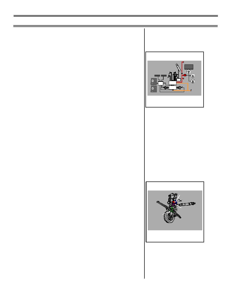
WHEEL BRAKE/ANTI-SKID BLOCK
DIAGRAM
1.
Description: electro-mechanically
controlled, hydraulically operated speed
sensing system
2.
Function
a.
Prevents wheel skids caused by
slippery surfaces or heavy braking
b.
Provides touchdown protection to
prevent locked wheels when landing
I.
Nose wheel steering (NWS) system 1.4.9.3.1.1
1.
Description: electrically controlled,
Sg 3, fr 8
hydraulically operated dual-gain power-
steering system
Electronic Control Box
Steering Motor
2.
Function: full-time, low-gain, selectable
high-gain nose wheel steering
Steering Collar
a.
Low gain provides +/- 12 degrees
either side of center for takeoff and
NOSE WHEEL STEERING MAJOR COMPONENTS
landing
NOSE WHEEL STEERING MAJOR
COMPONENTS
b.
High gain provides +/- 65 degrees
either side of center for aircraft
parking
(8-03) Original
Page 1-23


 Previous Page
