Aero Chapter 05/06 (TS) and 05 (ADV & IUT), Thrust and Thrust Curve Review
T-45 Aerodynamics Student Workbook
THRUST AVAILABLE
The thrust available from a turbofan engine is illustrated by the equation:
Ta = Q (V2 - V1)
Where:
Ta =
Thrust available
Q
=
Airmass flow in slugs per second (kilograms/sec in metric units)
V1 =
Inlet air velocity in feet per second
V2 =
Exhaust air velocity in feet per second
NOTE: The terms V1 and V2 are used interchangeably with Vin and Vexh respectively.
RPM EFFECT
One of the most obvious factors affecting thrust output is the speed of the rotor assembly, generally
referred to as revolutions per minute (rpm) of the engine. Because turbofan engines operate at very high
rpm, it is more convenient to refer to engine
revolutions as a percent of maximum
SEA LEVEL STANDARD DAY
allowable rpm or indicated rpm.
T-45
The indicated rpm is NOT an indication of
Theoretical
thrust or power. It is only an indication of
the rpm the engine is turning in relation to
100
the maximum allowable rpm. Rather, some
90
other engine variable indicators such as
engine pressure ratio or turbine discharge
75
pressure must be employed as an indication
of thrust being produced. As rpm increases,
55
both airmass flow (Q) and acceleration
through the engine (V2-V1) will increase.
40
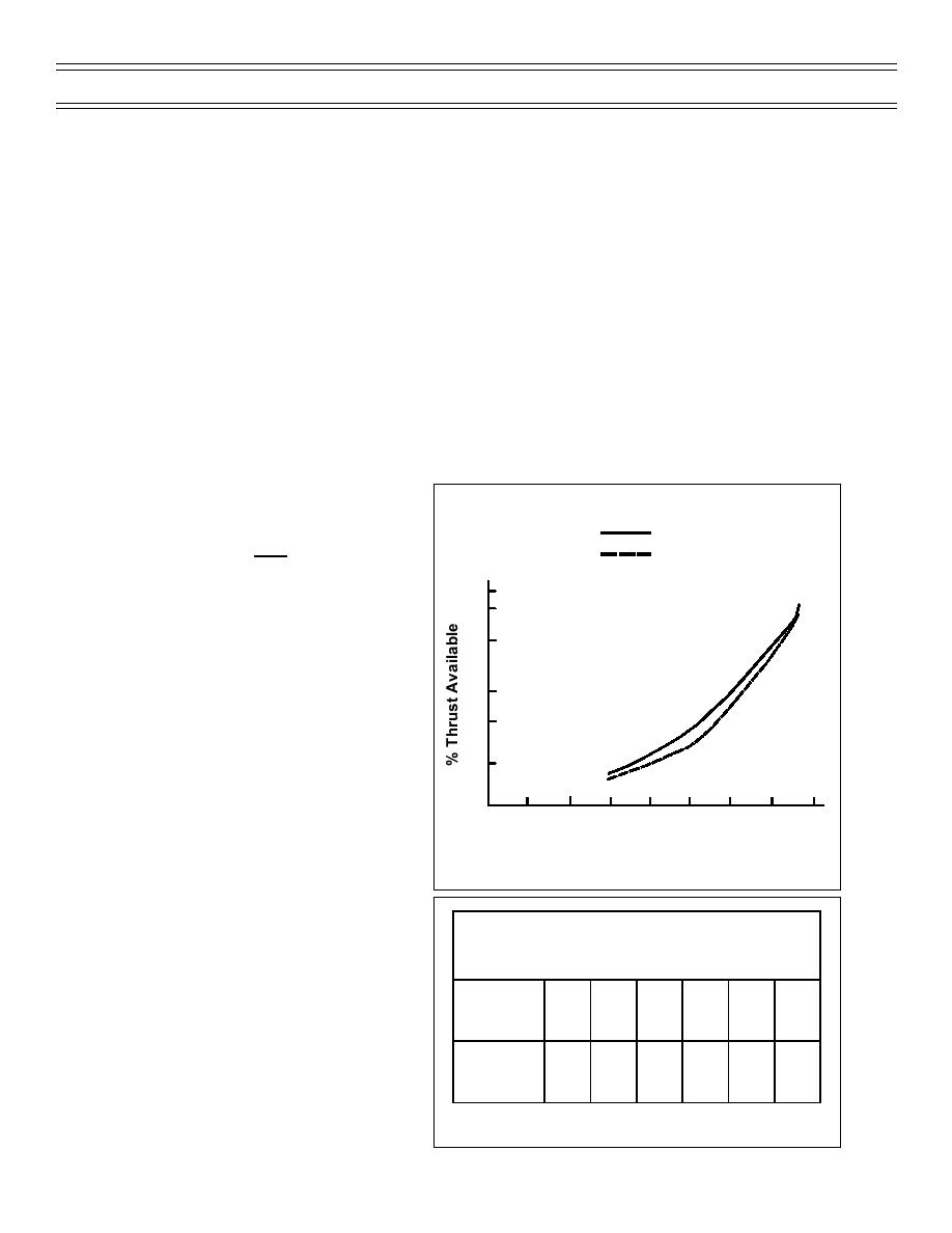
Thrust production does not relate linearly to
20
engine rpm (Figure 80). At low rpm, there is
very little change in thrust with a large rpm
change. Between 80 and 90% rpm, 25% of
20
30
40
50
60
70
80
90
100
the total thrust is produced. Between 90
% RPM
and 100% rpm, 30% of the total thrust is
produced. At high rpm, a small change in
Figure 80: T-45 RPM VS THRUST GRAPH
rpm will produce a large change in thrust.
The T-45 rpm-to-thrust output is tabularized
in (Figure 81). An indicated 100% rpm
JET ENGINE RPM VS. THRUST
produces an actual N2 rpm of 15,512.
AIRSPEED
% of MAX
100
99
95
90
80
70
The thrust available from turbojet and
RPM
turbofan engines is approximately
unaffected by changes in airspeed. From
% of MAX
the thrust available equation, acceleration
100
97
84
69
46
29
THRUST
through the engine (V2 -V1) will decrease as
inlet velocity increases. Thrust available
Figure 81: T-45 RPM VS THRUST MATRIX
(7-99) Original
Page 51


 Previous Page
