Introduction to T-45C Configuration
T-45C TS, ADV & IUT ENG-01
G. Brake system 1.4.10.3.1.1
Sg 3, fr 9
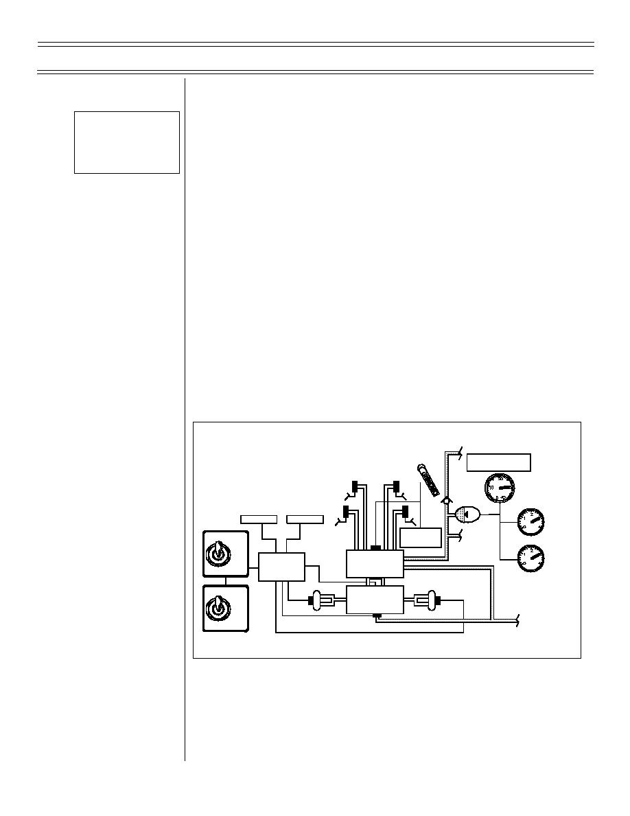
Fig 8: Wheel Brake/
1.
Description: conventional wheel-mounted, hydro-
Anti-Skid System Block
mechanically boosted self-adjusting braking system,
Diagram
with anti-skid
2.
Function: slows/stops aircraft and provides
directional control through differential braking if nose
wheel steering inoperative
3.
Control location
a.
Brake pedals: top of each rudder pedal, both
cockpits
b.
PARKING BRAKE handle: lower right
instrument panel, fwd cockpit only
H.
Anti-skid system 1.4.11.3.1.1
HYD 1
PA RK IN G
BR AK E
BRAKE ACCUMULATOR
BR AK E
INFLATION PRESSURE
M AS TE R
1300 PSIG
CY LIN DERS
S K ID
SKID
DE-SPIN
FLA P
ANTI-SKID
BRAKE
ACTUATOR
S YS TE M
ON
BRAKE
ANTI-SKID
CONTROL
OFF
CONTROL
VALVE
BOX
BRAKE
SPEED
SPEED
SENSOR
SENSOR
ANTI-SKID
ANTI-SKID
ON
VALVE
OFF
H Y D 1 R E TU R N
Figure 8: WHEEL BRAKE/ANTI-SKID SYSTEM BLOCK DIAGRAM
1.
Description: electro-mechanically controlled,
hydraulically operated speed sensing system
(9-98) Original
Page 1-16


 Previous Page
