Engine and Related Systems
T-45C TS, ADV & IUT ENG-04
Sg 1, fr 2
PRESENTATION
Lesson Organization
ENGINE AND RELATED SYSTEMS
I.
Engine system major component identification 1.4.6.3.1
* Majorcomponentsof
theT-45Cengine
* Engine operating characteristics
* Controls, switches, and indicators
LESSON NOTES
* Engine servicing
* Engine/aircraft interfaces
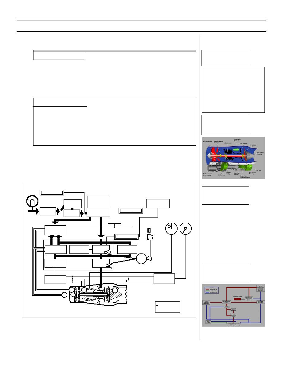
Direct your students to use the basic engine diagram (Figure 1)
and the basic engine block diagram (Figure 2) for reference
Sg 1, fr 3
Basic Engine Diagram
throughout this lesson.
A.
Engine: twin spool, medium bypass, axial flow turbofan
producing approximately 5527 lb of thrust
Sg 1, fr 4
CAUTION LIGHT
FUEL
LP PMP
Fig 1: Engine Fuel
FLOW
HP
System Block Diagram
Overspeed
Steam Ingestion
Fuel-Cooled
Governor
Bleed Valve
Oil Cooler
ADVISORY LIGHT
LP Fuel
M FUEL
Pump
HP Fuel Pump
Filter
PERCENT
RPM
EGT
Normal
Manual
Throttle
Lever
Manual Fuel
Control
CAUTION LIGHT
ACCEL
Throttle
Servo Pressure
Sub-Idle Fuel
Valve*
Switch
Control
Control Unit
Cam-
FUEL
box
Shutoff
CONTROL
Valve
(Fuel Trim)
Sg 1, fr 5
UNIT
Engine Lubrication
EGT/T2
System Block Diagram
Thermocouple
Engine Control
N1
Junction Box
Amplifier
P
T2
T6
1
P
0
Includes Initial
Shot Solenoid
Figure 1: ENGINE FUEL SYSTEM BLOCK DIAGRAM
Original (9-98)
Page 4-3


 Previous Page
