T-45C TS, ADV & IUT ENG-07
Aircraft Fuel System
IV. Aircraft interfaces 1.4.7.2
Sg 5, fr 2
Lesson Organization
A.
Inputs
FUEL SYSTEM
1.
Electrical system
* Major component
identification
* Operational characteristics
a.
Indicators: 28 VDC essential services bus
power source (boost pumps continue operating
* Controls, switches, and
indicators
for 30 seconds after generator loss)
* Aircraft interfaces
b.
Boost pumps: 28 VDC essential services bus
power source
(1) During starting (both ground and air starts),
energized by 28 VDC essential services
bus when the GTS start button is pressed
and will drop off line 30 seconds after GTS
shutdown unless generator comes on line
2.
Engine air system: Output of fifth stage high
pressure compressor filtered, regulated to 6.0 psi,
and distributed to fuel tanks for pressurization
B.
Outputs
1.
Engine starting system
Sg 5, fr 3
2.
Engine fuel system
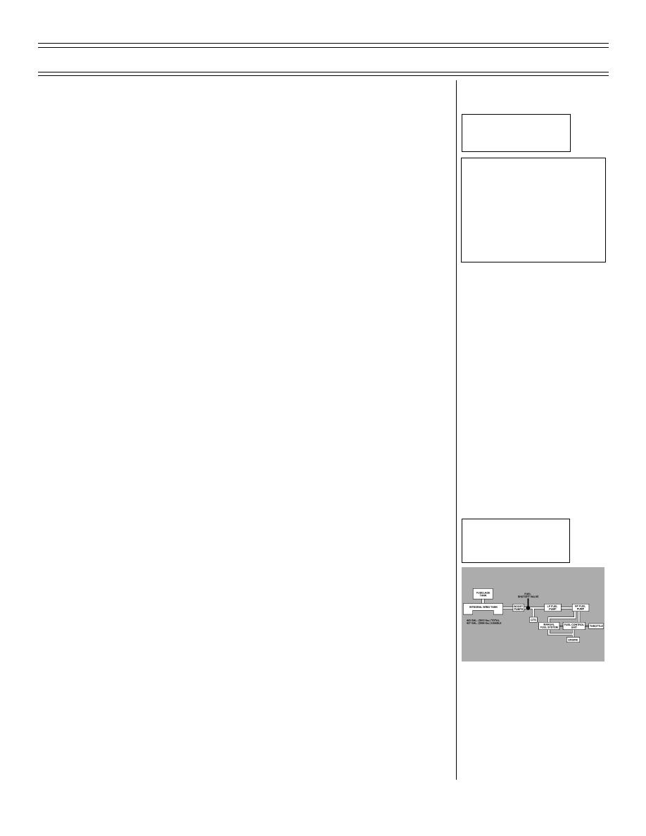
Simplified Fuel System
Block Diagram
3.
Centralized warning system (CWS): MASTER
ALERT light flashes concurrently with caution
advisory indications (FUEL, F PRES and BINGO)
4.
Intercom system (ICS): caution tone sounds in
headset concurrently with caution advisory
indications (FUEL and F PRES)
5.
Airborne data recorder system (ADRS): monitors
fuel quantity and fuel flow signals
Original (9-98)
Page 7-19


 Previous Page
