 |
|||
|
|
|||
|
Page Title:
Figure 6-2 T-6A Defined Wingtip Distances |
|
||
| ||||||||||
|
|  T-6A CONTACT
CHAPTER SIX
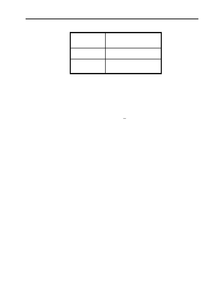
3/4 WTD
Where blue meets white on
the wing leading edge
2/3 WTD
Fuel cap
1/4 WTD
Where the canopy rail
visually bisects the wing
Figure 6-2 T-6A Defined Wingtip Distances
NOTES
1. Power settings are approximate and will vary with aircraft
weight, altitude, etc. Make corrections as needed. When mandated
by procedure to establish a specific power setting (as during the
4Ts, for example), setting power within +3% is acceptable. The
only exception is for procedures mandating a 4 to 6 percent power
setting to simulate the feathered condition.
2. Once established in the pattern, using greater than 30 AOB is
not recommended. Do not exceed 45 AOB.
602.
NORMAL LANDING PATTERN (USN)
The USN normal landing pattern is used at all naval air stations and outlying fields and can be
used to operate at most civilian fields. In order to understand the pattern procedures, you must
first have an in-depth knowledge of the pattern geometric shape and terms. Figure 6-4
LANDING PATTERN 6-3
|
|
Privacy Statement - Press Release - Copyright Information. - Contact Us |
