 |
|||
|
|
|||
|
|
|||
| ||||||||||
|
|  INTERCEPT PROCEDURES TEXTBOOK
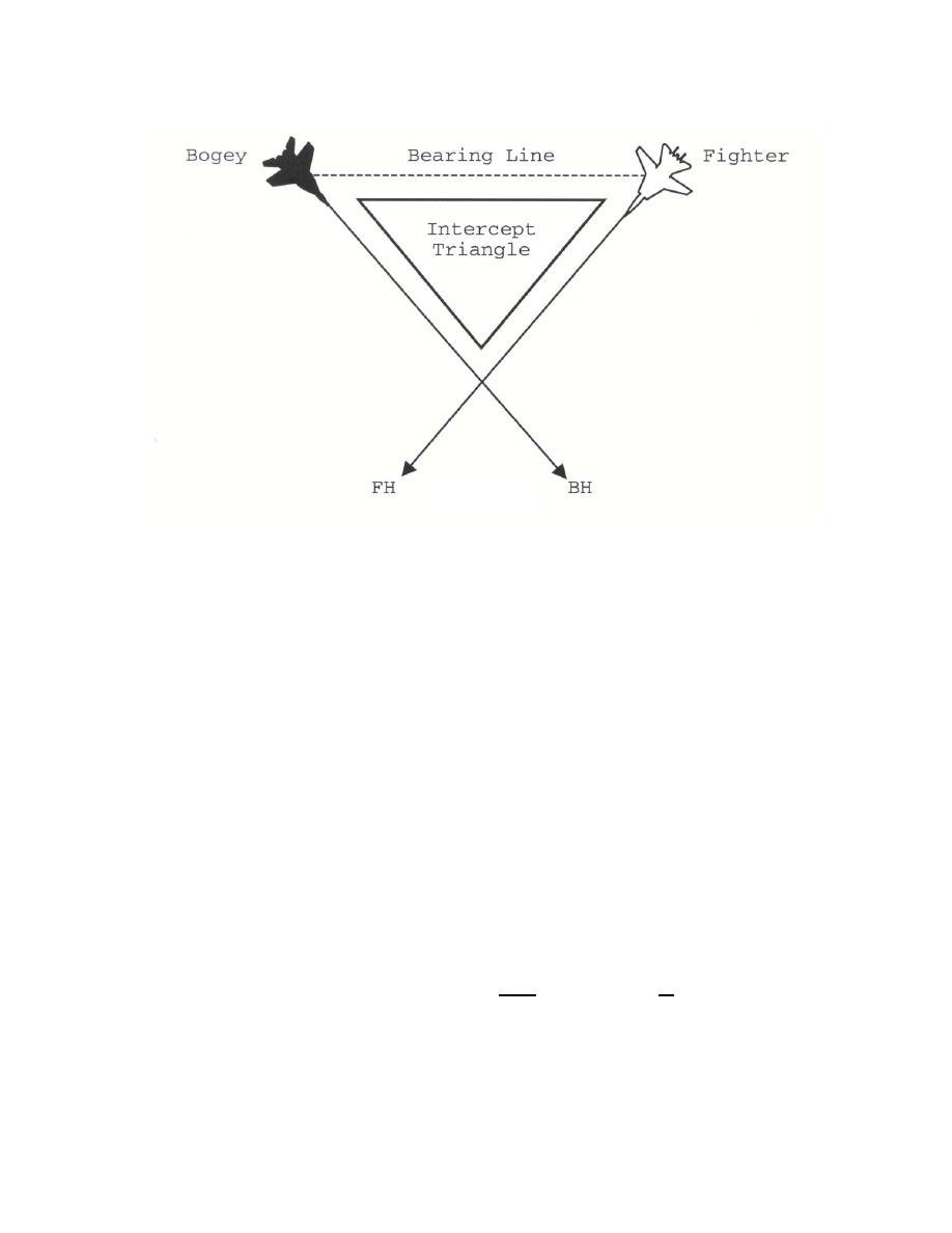
Figure 7
This intercept triangle is a useful tool in relating angles such as DTG, cut, AO and TA.
When combined with the fact that the three angles in a triangle add up to 180, a more complete
spatial picture can be obtained. TA, and consequently AA, can always be calculated if BB or
AO and DTG are known.
Flight Path Visualization Procedures
The procedure for flight path visualization must make use of the cut, DTG, and DOP. The
bogey heading and bogey bearing are received from the GCI controller. After receiving this
information, aircrew must determine the proper fighter heading fir intercept. Then the aircrew
can visualize the orientation of the fighter and bogey flight paths using the following five steps:
STEP 1: Visualize the fighter heading on the BDHI (for example, 180).
STEP 2: From the bogey heading (for example, 320) determine bogey reciprocal (140) and
visualize its position relative to fighter heading on the fighter's BDHI. Visualize a bogey's flight
path extending from the bogey's reciprocal to bogey's heading.
STEP 3: Compute the cut. The cut is the angle from fighter heading to bogey reciprocal
(180 to 140 = 40 Left cut)
STEP 4: Compute DTG by the recommended formula. 180 - cut (40L) = 140 DTG.
24
|
|
Privacy Statement - Press Release - Copyright Information. - Contact Us |
