 |
|||
|
|
|||
|
|
|||
| ||||||||||
|
|  BASIC FIGHTER MANEUVERING (BFM) THEORY
CHAPTER NINE
your airplane, the characteristics of the air-to-air arena, and finally, the bogey. First, we will take
a look at the basic component of "lift vector" and its affect on maneuvering.
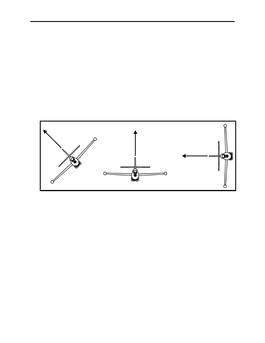
909. LIFT VECTOR
The lift vector is an imaginary line extending outward from the canopy and perpendicular to the
aircraft's wingspan (Figure 9-2). This line is simply a tool used to describe the plane in which
an aircraft is turning. During an engagement, the tactical placement of the aircraft's lift vector is
essential to achieving an advantageous position on the bogey. When a maneuvering fighter is
unable (due to position, energy state, or nose authority) to gain a positional advantage with
aircraft nose placement, the lift vector may be utilized. A defensive, neutral, or offensive fighter
can lead or lag a bogey with its lift vector. The lift vector can be manipulated to gain an
offensive (or improve a defensive) position. Once offensive, the fighter will need to transition to
pulling lead with the nose to obtain a valid guns solution.
Figure 9-2 Lift Vector
910. HORIZONTAL MANEUVERING
The most basic of all aerodynamic principles state that in order for an aircraft to maintain straight
and level flight, it must generate exactly 1"G" to overcome the effects of gravity. Because the
amount of lift required to maintain 1"G" flight is based on the weight of the aircraft (excluding
the effects of drag), the vector representing gravity remains constant as long as the weight of the
aircraft remains constant.
An aircraft in a turn at any angle of bank (AOB) must generate an additional load factor in order
to have the same effective lift. The required load factor increases because your lift vector is
moved out of the pure vertical. If we assume that the effective lift of the aircraft opposes gravity
(which is a constant force), the load factor will vary according to how tightly you want to turn
the aircraft. As you can see in Figure 9-3, both aircraft A and B are in level turns at a constant
true airspeed (TAS). Aircraft A is in an 80 AOB and aircraft B is in a 60 AOB. Because
aircraft A is turning at 80 degree AOB, his load factor is greater than aircraft B turning at a 60
AOB. Notice that because gravity and the effective lift remain constant, the resultant vector,
9-5
BASIC FIGHTER MANEUVERING (BFM) THEORY
|
|
Privacy Statement - Press Release - Copyright Information. - Contact Us |
