 |
|||
|
|
|||
|
|
|||
| ||||||||||
|
|  STUDENT GUIDE
VISUAL NAVIGATION
cross wind components, by first computing the distance off to seconds.) As a final note on head
and tail wind computations, note the Head/Tail wind component equation for any aircraft is
basically:
X
NM
=
Head/Tailwind (kts)
Time gained or lost (sec)
approx. time flown (min) since
min
last compensation update
7.7.2.5. As a result, whenever the approximate time flown in minutes is equal to the air speed of
the aircraft in nautical miles per minute, the head or tail wind is equal to the number of seconds
off of updated time. With this in mind, the Head/Tail wind equation can easily be used with any
aircraft at any airspeed.
EXAMPLE 7-3: A B-52 crew planned to fly VR-1616 at 360 knots TAS, which equates to 6 NM
per minute. If after 6 minutes of flight the crew finds themselves 15 seconds late, they can
assume a 15 knot headwind. If they found themselves 10 seconds late over three minutes, they
could assume by 6 minutes they would be 20 seconds late, indicating a 20 kt headwind. An EA-
6B Prowler planned at 420 knots TAS (7nm per minute) would assume 10 knots of headwind if
late by 5 seconds over three and a half minutes, or 10 seconds late over 7 minutes.
7.7.3. Totaling the Components:
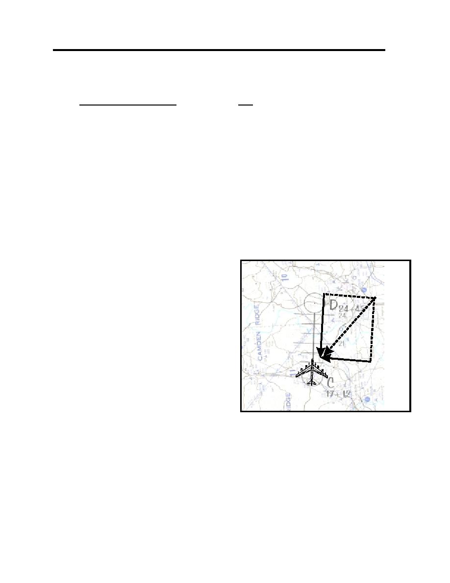
7.7.3.1. The final step in wind analysis via the
track method is to compute the total wind
15 kts. Head wind
affecting the aircraft. As computation of the out
bound heading and airspeed is necessary to
complete each Two-Minute Prior call, prompt
total wind computation is necessary.
TOTAL WIND:
7.7.3.2. With the basic components derived,
125 degrees at
20 kts.
determine the total wind by using the
proportions shown in figure 7-5. An alternate,
though less accurate, method is to compute the
10 kts Cross wind
wind magnitude by adding half of the smaller
component to the larger component. Using this
technique, compute accurate bearings through
graphical analysis, as described in Unit 5 of the
Figure 7-4
T-34 VNAV text (see figure 7-4). Grading
standards are 30 and 10 kts. As the two-
minute prior call requires total wind computation to determine outbound heading and airspeed,
students must be fluent in these computations. Be careful of the common error of mistaking the
wind direction by 180, which effectively doubles the wind's effect on low-level navigation.
7-7
|
|
Privacy Statement - Press Release - Copyright Information. - Contact Us |
