 |
|||
|
|
|||
|
|
|||
| ||||||||||
|
|  INSTRUMENT NAVIGATION
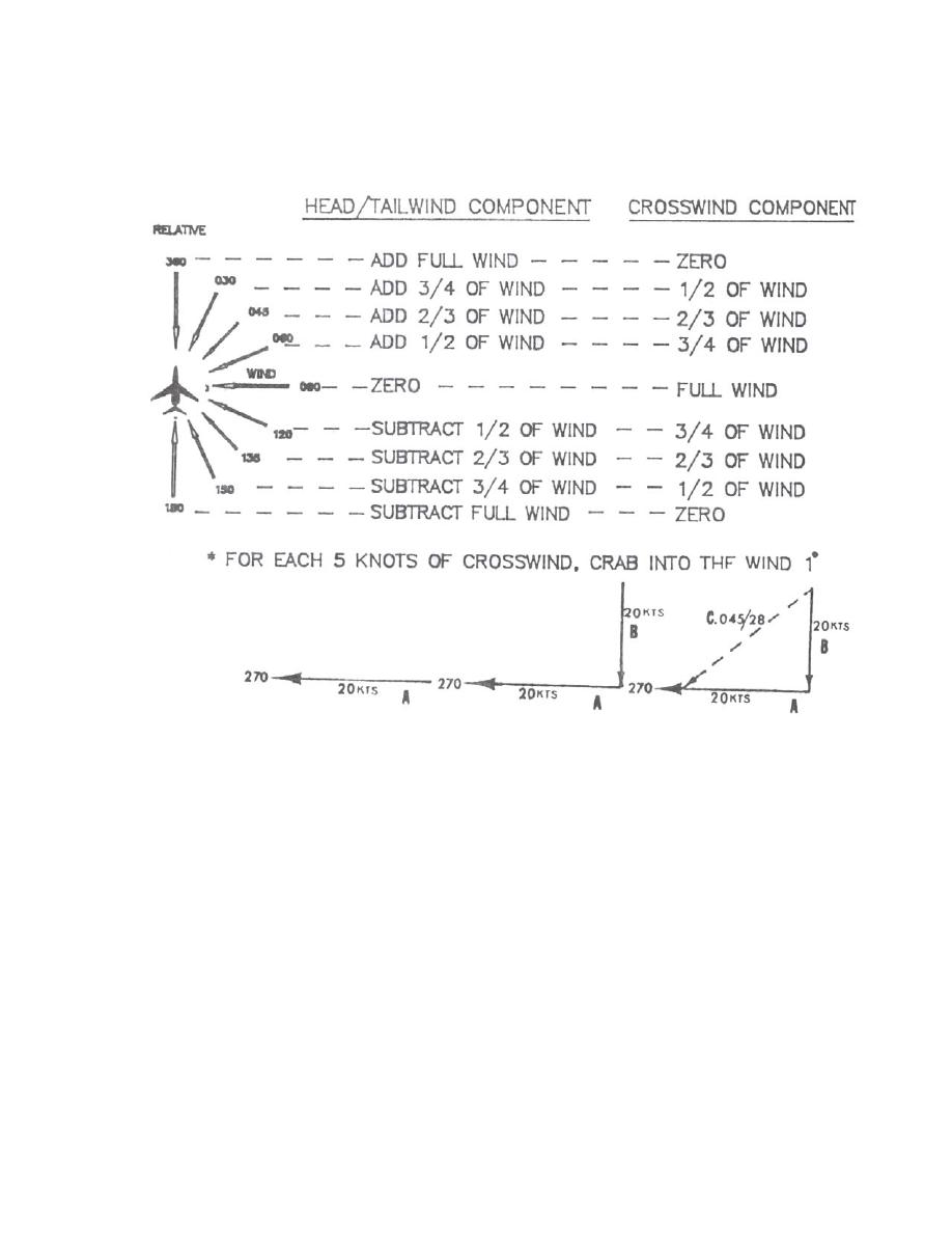
If you were to work this out geometrically you would find that here we used a simplified
example utilizing a right isosceles triangle. If you check your answer with the CR-2, it will be
very close.
Figure 37
Another approach to wind analysis can be applied just by knowing the respective Head/Tail
Wind Components and the Left/Right Crosswind Component. Based on your aircraft's magnetic
course, determine the quadrant which coincides with your respective wind components. Once
the quadrant is determined, further subdivide this into eights. If both components are of equal
valve, the wind direction will correspond with a heading 45 from the aircraft's course; otherwise
the wind direction will be from the eighth segment (sector) which has the larger component. If
one component is twice as large as the other, then the wind direction will subdivide the sector of
the larger component, etc. A relatively simple yet effective manner of calculating the velocity
vector can be accomplished by utilizing the following formula:
Larger Component Plus Smaller Component = Total Wind Velocity
In Figure 37, this formula yields a wind velocity of 20+(x20) 30 knots.
3-28 RADIAL TRACKING AND COURSE CONTROL
|
|
Privacy Statement - Press Release - Copyright Information. - Contact Us |
