 |
|||
|
|
|||
|
|
|||
| ||||||||||
|
|  HELICOPTER AERODYNAMICS WORKBOOK
CHAPTER 2
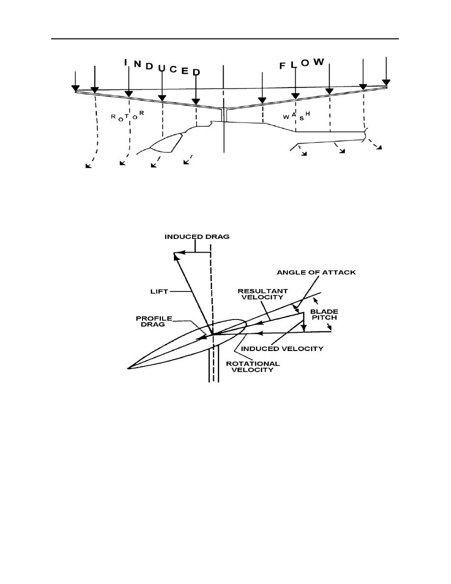
Figure 2-5
The Momentum Theory adequately provides an explanation for no-wind, hovering flight, but
it does not cover all of the bases.
Figure 2-6
The Blade Element Theory picks up where the Momentum Theory leaves off. The
conditions at the blade element are diagramed in figure 2-6. The blade "sees" a combination of
rotational flow and downward induced flow (figure 2-7) called relative wind, a downward
pointing velocity vector. The AOA is the angle formed between the relative wind and the chord
line, and the pitch angle is formed between the TPP and the chord line. Lift, which is the total
aerodynamic force perpendicular to the local vector velocity, or relative wind, is tilted aft. This
rearward component generated by lift is induced drag, formed from the acceleration of a mass of
air (downwash) and the energy spent in the creation of trailing vortices. The remaining arrow
labeled profile drag is the result of air friction acting on the blade element. Profile drag is made
up of viscous drag (skin friction) and wake drag, which is the drag produced from the low
velocity/low static pressure air formed in the wake of each blade.
ROTOR BLADE AERODYNAMICS 2-5
|
|
Privacy Statement - Press Release - Copyright Information. - Contact Us |
