 |
|||
|
|
|||
|
|
|||
| ||||||||||
|
|  T-34C AIRCRAFT SYSTEMS FAMILIARIZATION
CHAPTER NINETEEN
WORKBOOK
airborne. The safety switch on the nose strut enables the rudder shakers in flight and the beta
release while on the ground.
Position Indicator Switches
Position indicator switches are micro type switches located in the wheel wells. These switches
activate the gear position indicators in each cockpit and the external down position indicator
lights. The left main landing gear UP position switch activates the air conditioner condenser
blower any time the gear is not up and the air conditioner is operating. The nose landing gear UP
position switch activates the landing light fault light and the master caution light when the gear is
up and the landing lights are on.
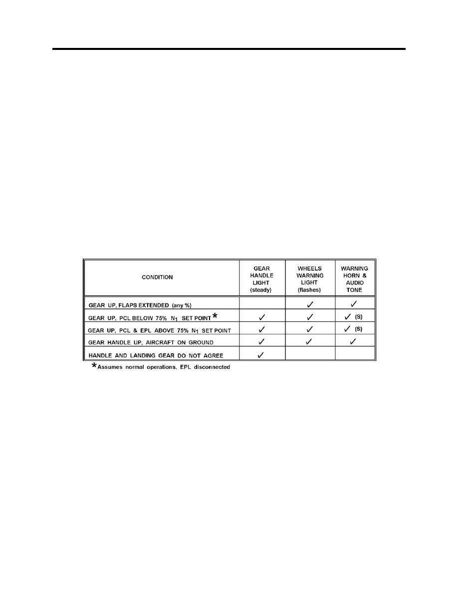
1903. LANDING GEAR WARNING SYSTEM
The landing gear warning system consists of a horn behind the front seat, a 1000-Hz audio tone
in the ICS, a steady red light in the landing gear handle and a flashing red landing gear WHEELS
warning light on the instrument panel. This system is designed to alert the pilot of an unsafe
condition and will be activated if any of the following conditions exist:
The warning horn and audio tone may be silenced, but only under certain power-off conditions--
noted by "(S)" in the chart. When allowed, silencing is accomplished by depressing the button
(Figure 19-3) labeled WARNING HORN SILENCE, adjacent to the landing gear handle. This
does not affect the warning lights.
Position Indicator
The position of the landing gear is shown by three individual indicators, one for each gear,
located on the instrument panel in both cockpits, lower left side, just to the right of the gear
handle. Each indicator can display any one of following three conditions.
1.
Cross-hatching (barber pole) related gear is in any unlocked position (gear in transit, not
down and locked or not up and locked) or the electrical system is not energized.
2.
The word UP displayed - related gear is up and locked.
LANDING GEAR SYSTEMS 19-7
|
|
Privacy Statement - Press Release - Copyright Information. - Contact Us |
