 |
|||
|
|
|||
|
|
|||
| ||||||||||
|
|  CHAPTER THIRTEEN
T-34C AIRCRAFT SYSTEMS FAMILIARIZATION
WORKBOOK
1302. ATTITUDE SYSTEM
Attitude Indicator
The attitude indicator provides the pilot with a visual reference of the aircraft's attitude during all
types of flight, including aerobatic and inverted flight. Attitude indicators are in the center top of
both instrument panels and receive attitude signals from a single 115 VAC gyro located in the aft
cockpit aft of the left console. The indicators are accurate through 360 roll and + 82 pitch.
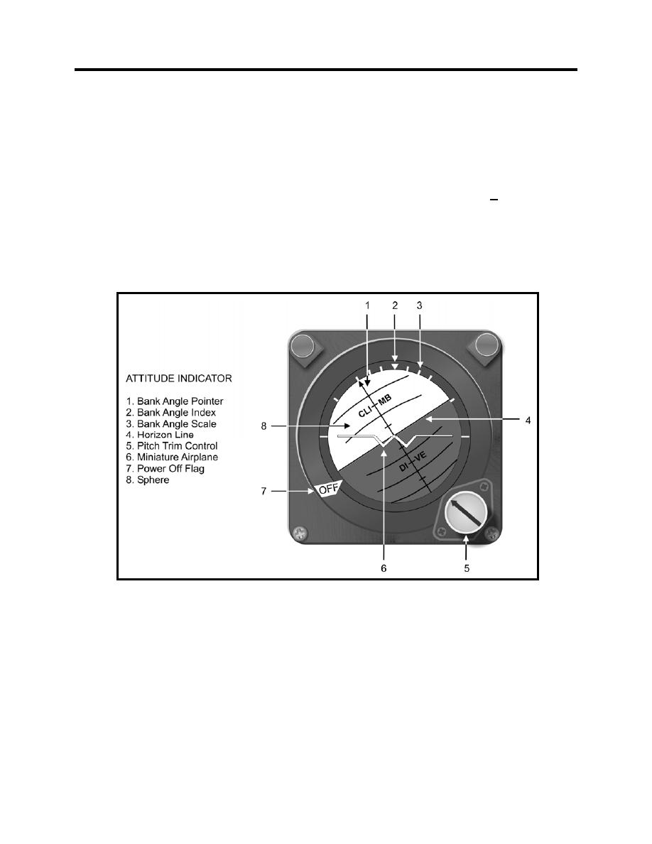
Pitch and roll are shown by motion of the indicator's sphere in relation to a miniature aircraft.
The horizon of the sphere is a white line. The upper half of the sphere, labeled CLIMB, is gray
while the lower half, labeled DIVE, is black. Horizontal graduation lines are 5 apart. A bank
angle pointer is used in conjunction with a bank angle index and scale to indicate roll attitude.
Both the gyro and indicators receive 115 VAC when either inverter is turned on.
Figure 13-1 Attitude Indicator
Fast Erect
Above the upper left corner of each attitude indicator is a red button labeled FAST ERECT. To
correct for gyro precession while airborne, press and hold the FAST ERECT button. This will
apply a higher voltage to the torque motor, accomplishing what automatically takes place when
AC power is initially applied. When in flight, fast erect shall only be accomplished when level
and not accelerating.
13-2
ATTITUDE, TURN AND SLIP, AND ACCELEROMETER SYSTEMS
|
|
Privacy Statement - Press Release - Copyright Information. - Contact Us |
