 |
|||
|
|
|||
|
Page Title:
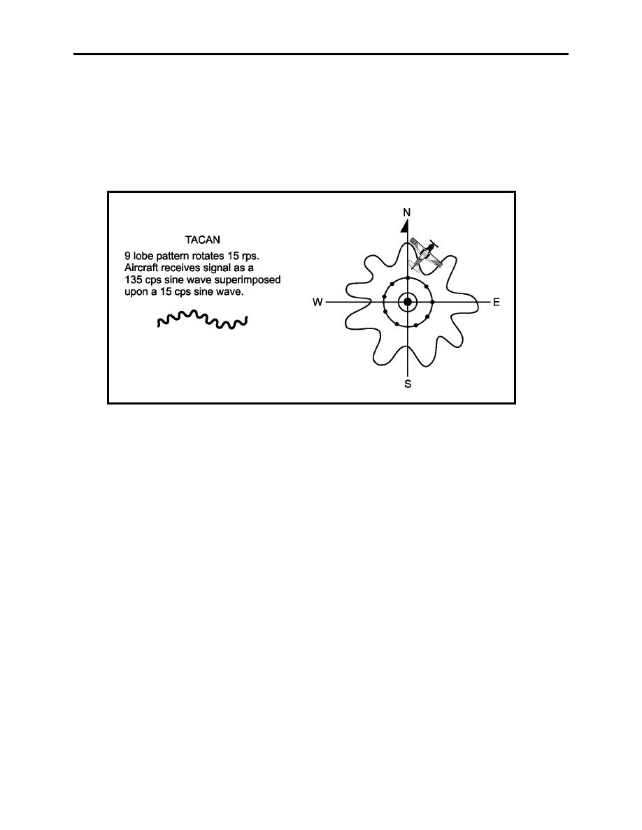
Figure 1-12. Fine Azimuth Pattern |
|
||
| ||||||||||
|
|  CHAPTER ONE
INSTRUMENT FLIGHT RULES WORKBOOK
antenna rotation (360 divided by nine pulses). The airborne equipment electronically measures
the time lapse between the main reference pulse and the maximum amplitude (signal strength) of
the 15 Hz rotating signal pattern (Figure 1-13). This determines the aircraft's bearing from the
station within a 40 sector. Then, the time lapse between the auxiliary reference pulses and the
maximum amplitude of the 135 Hz signal is measured to determine the aircraft's position within
the 40 sector. The accuracy of this measurement determines the position of the aircraft relative
to the station within plus or minus one degree.
Figure 1-12 Fine Azimuth Pattern
1-16 INTRODUCTION TO AIRBORNE NAVIGATION AND COMMUNICATIONS
EQUIPMENT AND PRINCIPLES OF OPERATION
|
|
Privacy Statement - Press Release - Copyright Information. - Contact Us |
