 |
|||
|
|
|||
|
|
|||
| ||||||||||
|
|  Slow-Speed Flight, Stall and Spin, and AOA System
T-45A/C TS, E2-C2, ADV & IUT Aero-03
c.
Reduce boundary layer growth by reenergizing
boundary layer
NOTE: The vortex generators were installed on the
T-45 to help airflow characteristics during high-
speed (high Mach) flight. However, they also
improve slow-speed airflow characteristics.
5.
Stall strips
Sg 1, fr 13
Fig 5: Stall Strips
a.
Located on inboard slat and wing leading edges
to improve stall characteristics of the aircraft
b.
Cause a premature flow separation at the wing
root, contributing to a root stall.
c.
Slow the outward progression of stall
d.
Contribute to more consistent root stall at all
flap/slat settings
e.
Improve handling qualities at stall by controlling
roll-off
f.
Do not reduce maximum lift coefficient
6.
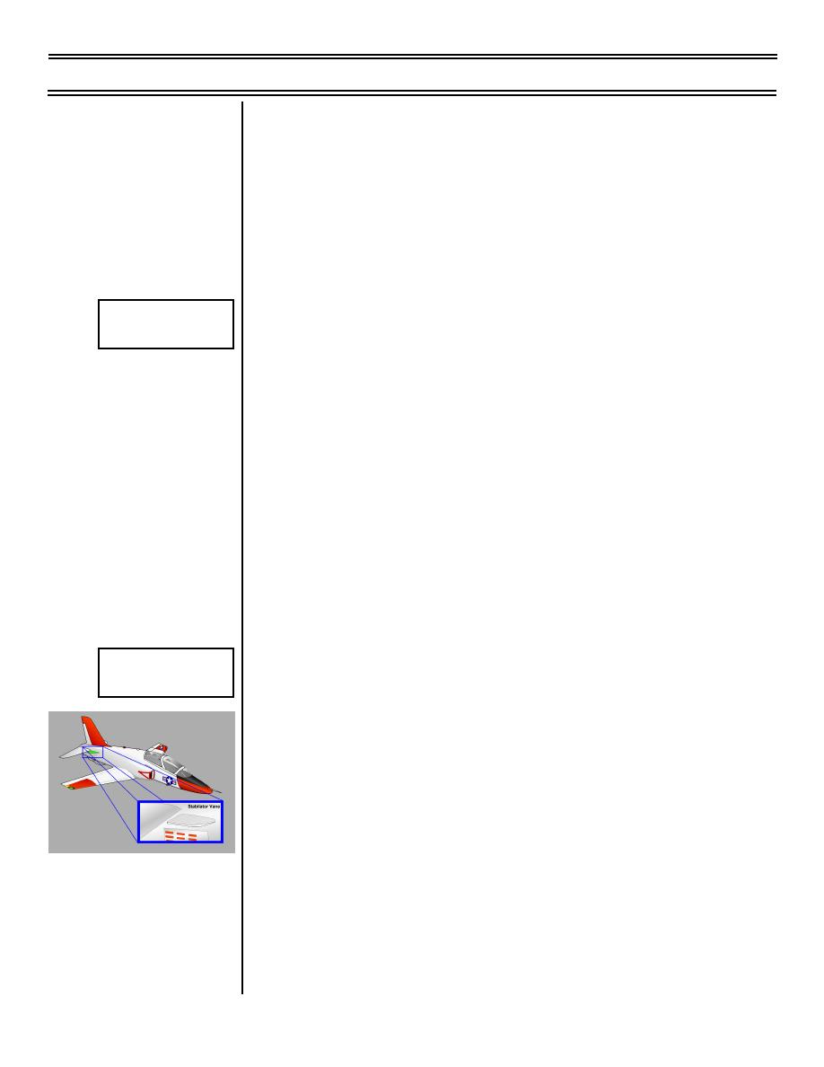
Stabilator vanes
Sg 1, fr 14
Stabilator Vanes
a.
Located on both sides of fuselage, just forward
of stabilator and above speed brakes
b.
Generate a vortex which passes below the
stabilator
c.
Vortex energizes flow over stabilator lower
surface, keeping it effective, particularly at
maximum leading-edge-down stabilator
deflection
NOTE: The overall effect of high-lift devices is to
cause the root to stall at a lower AOA than the tip,
thus giving the T-45 root stall characteristics.
(9-99) Original
Page 3-10
|
|
Privacy Statement - Press Release - Copyright Information. - Contact Us |
