Aero Chapter 03, High AOA/Stall/Spin
T-45 Aerodynamics Student Workbook
In a swept wing aircraft, high-speed stall entry tends to be more abrupt in onset and severity than in the
low-speed regime stalls. Also, at high airspeeds when rapidly flown into stall, many swept wing aircraft
designs will enter a departure, which is loss of aerodynamic stability along one or more axes of flight:
lateral, longitudinal, vertical.
A SUMMARY OF SWEPT WING :
ADVANTAGES
DISADVANTAGES
Permits higher speeds
Develops less CL
Structurally stronger for a given span
Prone to tip stall
Spanwise flow
Leading edge vortexing
Uncontrolled pitchup in some aircraft
Subject to departures/spins
High induced drag at low speed
At subsonic speeds, maximum lift is lower and induced drag higher than in straight wings. As a
consequence, the aircraft is more “cocked up” in landing approaches. Sweep back reduces effectiveness
of trailing edge devices such as ailerons and flaps. Thus, swept wing aircraft tend to have higher
approach speeds and need more power during the approach. They, therefore, have less excess power
and can enter a stall on the back side of the power curve more easily than straight wing aircraft.
AIRFLOW ON THE WING
The swept wing produces less lift at
all speeds than the straight wing with
similar wing area and chord. Tip
stalling is a problem on swept wing
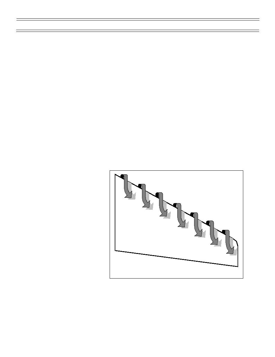
aircraft due to spanwise airflow that
is exacerbated by leading edge
vortexing (Figure 46), air that jumps
from the high pressure on the bottom
of the wing around the leading edge
to the top of the wing and moves
toward the wing tip. This spanwise
flow reduces the wing tip’s laminar
flow and contributes to tip stall.
Increasing angle of attack increases
the leading edge vortexing,
spanwise flow, and tip stalling
tendency. Stall fences were an early
solution to spanwise flow and
Figure 46: LEADING EDGE VORTEXING
illustrate one method of reducing the
problem. The tip stalling causes the
center of pressure of the wings to
move in and forward as the AOA increases. In turn the AC moves forward and closer to the CG which
reduces the longitudinal stability (Figure 47). Also, the loss of aileron effectiveness reduces lateral
stability.
(7-99) Original
Page 28


 Previous Page
